-
Products
+
-
Products
- New Products
- AV over IP Solutions
- Unified Communication & Collaboration Solutions
- Digital Video Processing Solutions
- Control Systems & Software
- Matrix Switchers
- HDMI Switchers
- HDMI Distribution Amplifiers
- Wireless AV Solutions
- HDMI over CAT6 Extenders
- HDMI Fixers & Boosters
- HDMI Cables
- Active Optical HDMI Fiber Cables
- Audio Solutions
- Accessories
-
Key Digital AV Over IP Systems
- AV Over IP Systems Overview
- AV Over IP Products
- DIY AV Over IP Systems
- Control Apps and Software
-
-
Markets & Solutions
+
- KD University
-
Resources
+
-
Press Resources
- Press Releases
- Key Digital in the News
- Hires Artwork
-
Sales Resources
- Market Case Studies
- Video Resources
- Sales & Tech Presentations
-
- About Us +
- Contact
Analog Matrix Switching vs. ATSC Encoder Matrix Switching
By Mike Tsinberg - May 2012
Two methods of analog matrix switching, traditional baseband analog switching method and the ATSC compressed method, which are used in commercial installations, recently warranted an important comparison.
The ATSC compressed method came into being as a result of inexpensive ATSC encoders introduced over the past two years. Thus far ATSC encoders were used only in a broadcasting environment where HDTV 1080i/720p signals were compressed by a factor of 100 to fit broadcasting limitations of the FCC of 6MHz RF spectrum. The average price of such high quality encoders for broadcasting applications ranges from $50,000 to $300,000. Recently ATSC encoders have been brought to market in the $2,500 price range. This development allows such encoders to not only be used in broadcast studios, but also in a regular commercial environment. However, ATSC is an open system without any copy protection such as HDCP and as a result the only video input in residential commercial installations that can be used with ATSC encoder is analog component video. HDMI cannot be used in any environment without HDCP copy protection. In this regard matrix switching created with ATSC encoders can only be compared with analog component matrix switchers. ATSC compression depends greatly on spatial compression with special emphasis on temporal compression. The temporal compression is the most expensive part and in order to achieve a lower cost, the ATSC encoder’s most significant video compression artifacts will appear in the area of temporal manipulation or motion.
In the ATSC encoder method, additional encoders need to be added in order to increase the number of inputs to the system. The principle on which the system works is very simple: each “input” becomes an independent 6 MHz RF channel available in the single coaxial cable while each “output” is an actual TV tuned to the specific RF channel “input.” Therefore, in order to change the “inputs” for each “output” one simply needs to tune the TV to a different channel. In traditional analog matrix switchers, the matrix switcher established individual connections between any of the inputs and outputs by utilizing a cross point switcher technique in the actual hardware of the matrix switching device. Connectivity between the matrix switcher, the source equipment, and the TVs can be accomplished using traditional coaxial YPrPb plus L/R Audio or the significantly more desirable CAT5 cable. The comparison in this paper will be between ATSC encoders connected via coaxial cable and TVs (connected to the same cable and analog matrix switcher using CAT5 cables to connect to each TV).
ATSC encoder method:
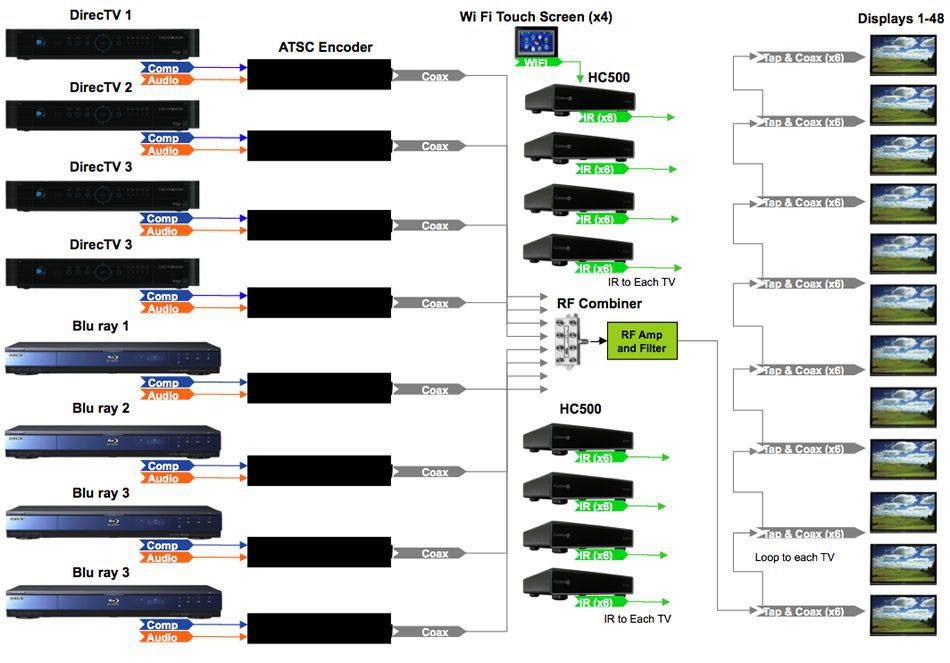
The example below shows an 8x48 Matrix switcher utilizing ATSC Encoders. RF outputs of all 8 ATSC Encoders are combined through an RF combiner into a single Coaxial cable. That cable is then distributed to all 48 TVs. Each TV needs to use an RF Tap to get an RF signal. After every RF Tap, the RF signal gets 3 dB weaker which explains why the initial RF power needs to be sufficient in order to deliver enough energy for the last TV. The drawing below shows extra RF amplification. Quite often a bar or restaurant installation of this kind will use the same brand of TV. Careful attention has to be paid to the control system since it will control each TV independently and reliably. In this configuration the TV control is the only way to switch the RF channel “inputs” for each of the TVs in this encoded system. We chose Control4 HC500 base stations and WiFi touch screen for this operation. An installer would need 6 of HC500 with 8 control ports to access each TV individually.
See picture below:

![]() Positives for ATSC based Matrix Switcher:
Positives for ATSC based Matrix Switcher:
- One coaxial RF cable can be used to snake among 48 TVs. Each TV needs an RF Tap unit to tap-off the RF signal from the coaxial cable
- Easy to add/remove “inputs” - add/remove ATSC Encoders and easy add/remove “outputs” by simple add/remove TVs connected to the coaxial cable
![]() Negatives for ATSC based Matrix Switcher:
Negatives for ATSC based Matrix Switcher:
- Heavy compression by factor of 100 using inexpensive semiconductor solutions – kills video quality especially in regards to motion
- Inexpensive modulation and filter solution for RF filters limits the total amount of TVs hooked up. To increase the number of TVs you may need to use professional RF Taps, Amplifiers and Filters that are labeled “Broadcast quality manufactured” not listed above and which make it significantly more expensive.
- Having a length of over 500 feet may require additional special RF amplifiers and filters
- Termination of RF connector has to be extremely well made in order to pass the fragile ATSC signal
- You must have individual control for each TV for tuning to any of the ATSC channels in order to access encoded sources “inputs.” There is no path for control in this environment – hence, an installer must use IR or RS232. Control for TVs can only be accomplished independently. Therefore, this kind of RF system requires a control system for individual tuning of each TV. The control system must be individually addressable since most TVs in such installations are usually from same manufacturer.
- No path for 1080p. The system is 1080i or 1080p/24 at max. That is the same limitation for ATSC or analog matrix systems
- No path for 3D. ATSC only supports 2D. That is the same limitation for ATSC or analog matrix systems
- Only Analog Component video can be used at the source due to no Copy protection in ATSC
- Since wiring is all coax cable this system cannot be upgraded to HDMI matrix at a later time. An HDMI matrix can only be achieved by individual HDMI cables from the matrix switching point to each TV or by individual CAT5 cables
- The switching time can be slow due to the tuning time and ATSC decoder settling time for each TV
- Audio for each TV can be only as associated with original channels or muted at TV end by control system. If you need independent switching for Audio additional Audio matrix switcher needs to be brought in front of ATSC Encoders.
- Analog Sunset will limit using of some content. That is the same limitation for ATSC or analog matrix systems
Analog Matrix Solution:
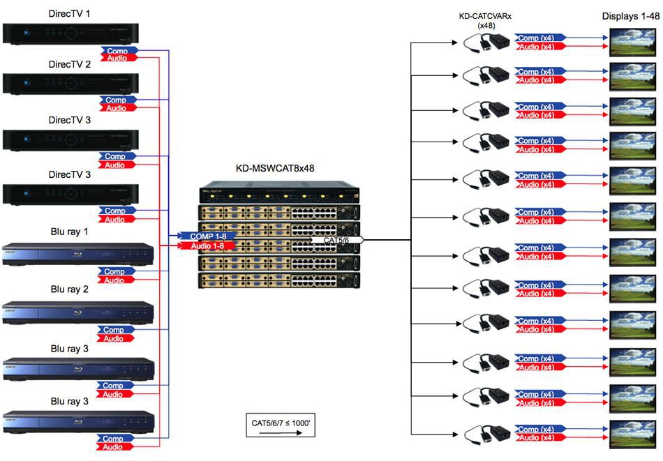
The picture below shows an 8x48 example of a full analog matrix switcher using 6 MSWCAT8x8 matrix switchers networked together to achieve 8x48 functionality. All Inputs are Component cables from the source to the switcher while all outputs are CAT5 cables connected from the switcher to CAT5 to Component Baluns (extenders). The CAT5 cables carry uncompressed Component HDTV and Audio for the displays. The switcher can be controlled using the unit’s front panel push buttons. There is no need for an extra control system. As an added bonus one can access any source on any display at any time quickly without relying on the speed and placement of encoded channels.

![]() Positives of Analog Matrix Solution:
Positives of Analog Matrix Solution:
- There is no compression whatsoever. The delivered video quality to each display is identical to the source
- System can grow to any size without special requirements for RF filtering or modulation
- Each TV is connected via single CAT5 to the matrix switcher
- Each CAT5 can be up to 1000 feet
- Each TV can have Video, Audio, RS232 and IR via that single CAT5. No additional wiring necessary
- Audio can be independently switched without requirement for additional switcher
- The switching is done at Matrix switching – no need to control tuning of the TV’s. Switch control can be done locally at the switcher
- The switching time is instant
- Since wiring is all CAT5 cables to each TV this system can be upgraded to HDMI matrix in the future. HDMI matrix can be achieved either by individual HDMI cables to each TV or existing individual CAT5 cables to each TV from past analog system
![]() Negatives for Analog Matrix System:
Negatives for Analog Matrix System:
- System configuration decision for inputs and outputs has to be done before installation. Very hard to change matrix size once it installed
- No path for 1080p. The system is 1080i or 1080p/24 at max. That is the same limitation for ATSC or analog matrix systems
- No path for 3D. That is the same limitation for ATSC or analog matrix, but analog systems wired with CAT cabling can easily be upgraded
- Analog Sunset will limit using of some content. That is the same limitation for ATSC or analog matrix systems
- No snake of the cable between TV’s. Each TV need separate CAT5 cable to the Matrix
Conclusion:
This white paper was created to help clarify, compare, and contrast the definitive differences between installation options of an ATSC Coax Encoded system; versus a full matrix analog switching solution. In our history we have seen many applications that have tried both methodologies, with the majority of ATSC only systems being used exclusively for non-HD content. However, as content improves and transforms into 3D we are seeing more attention to detail being given. Additionally the quality of such a system, utilizing a full matrix switching solution, is also rapidly improving and is becoming a reality. Another important factor for any installer considering a system utilizing the technologies mentioned in this white paper is that control is no longer optional, rather it is mandatory. Full matrix solutions work with increased fluidity when they utilize a control system and deliver an automated and effortless way of navigating through content to the end-user. They also allow the end-user to get exactly the TV program they want on any display at any time or in the context of this paper any sports event to appear on all displays simultaneously within seconds.
Key Digital Matrix Switching Solutions
Discover Key Digital Matrix Switching Products and Solutions


